
Look at all the pretty colors.
Look at all the pretty colors.
This project is YET ANOTHER custom-built solution designed to bring animations, visuals, and simple games to life on hub75 RGB LED matrix panels using an ESP32-S3 microcontroller. Whether you are looking to assemble your own hardware setup from scratch or simply enjoy the cool desktop toy, maybe this will interest you. It is a work in progress but it seems to function enough to mess around with.

If you want to check out the code, contribute, or fork this for yourself, you can find the repository and related resources below:
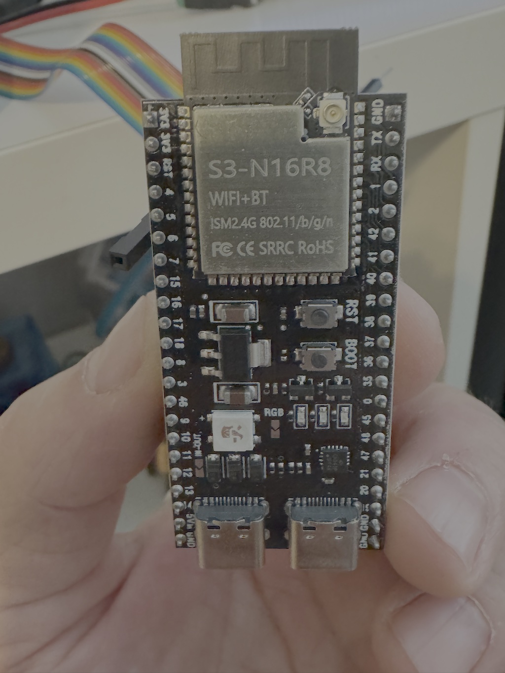
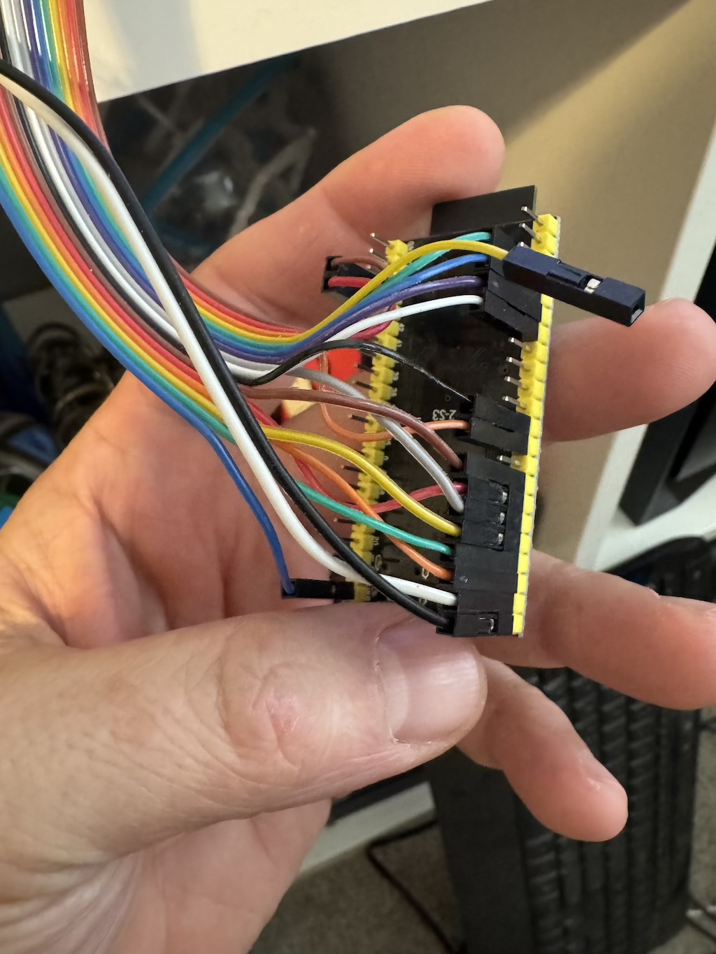
You can connect an ESP32-S3 directly to the 64x64 matrix panel, but you will have interference from Wi-Fi and see glitching on the screen. It’s not a game breaker. It will work fine. But you will see some static and gitching pixels that you’ll drive you crazy and you will wonder why is it doing that. You can minimize the glitching by ensuring you share ground between the ESP32-S3 and the panel's power source.
The reason is that the ESP32-S3 signal pins are using 3V and the hub75 connector on the matrix panel is expecting 5V.
The solution is to use level shift chip like the Texas Instruments SN74AHCT245N which you step between 3V and 5V.
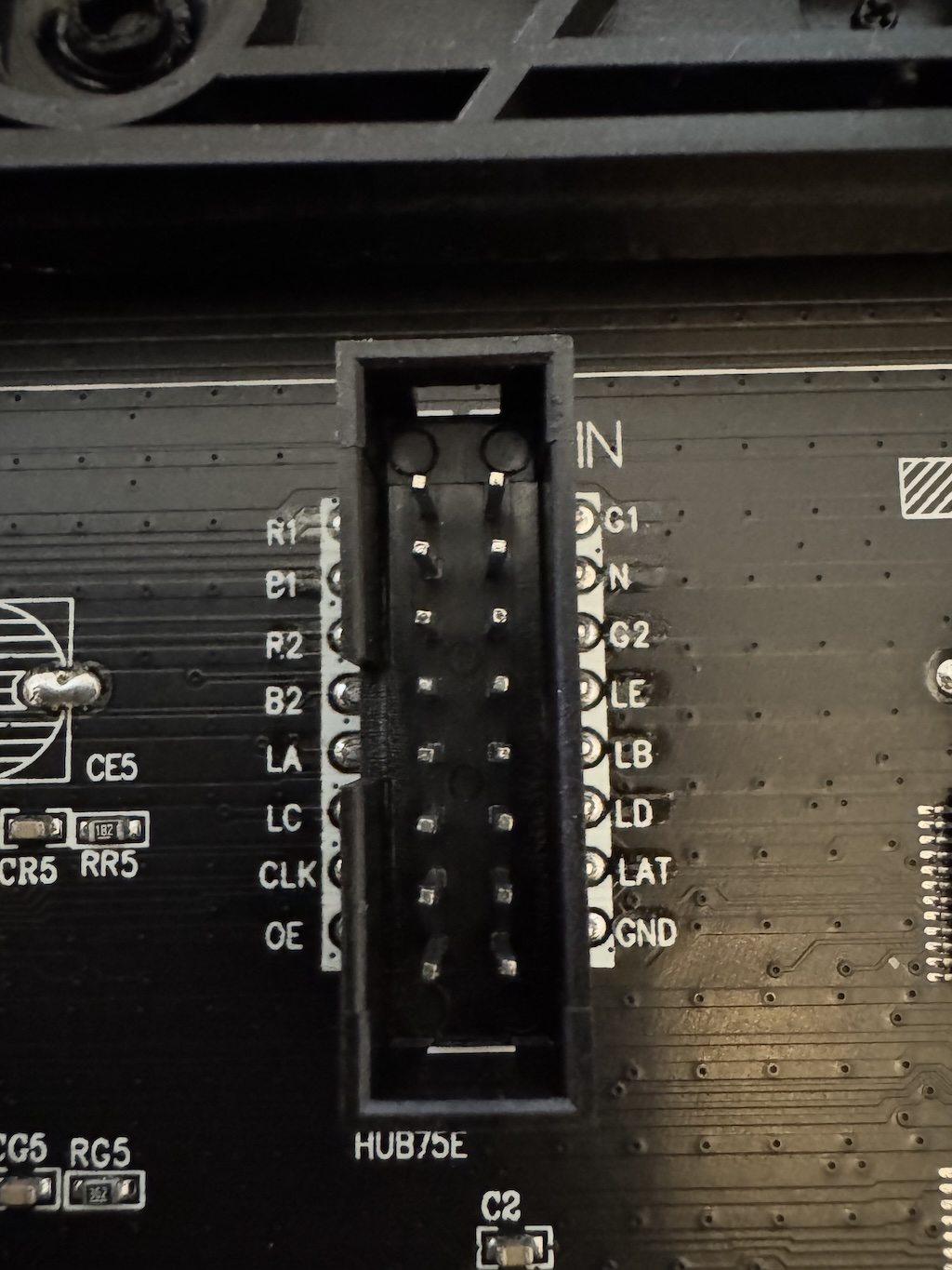
This is the matrix panel side. Note the "E" (Labeled 'LE' here) address is on pin 8. This matters if you purchase an interface board (rather than assemble one like this). Just to understand the layout, R1 is pin 1 and G1 is pin 2. You will need to know this pin layout when you set the software -- We have to tell the software how the hardware is wired together.
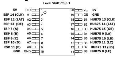
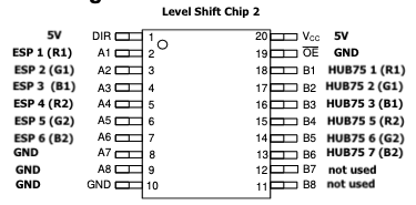
Because we have 14 pins to level between 3V and 5V... We have the five address lines, ABCDE, then we have clock, latch, and output enable. Finally there are two sets of RGB lines that allow the panel to do two updates at the same time that brings all the pins that you need to level to a grand total of 14. The chip can only do eight pins, so we need two chips to handle the 14 pins and the two unused pins on the 2nd level shift, we just tie the ground on the input side and it’ll stop them from being little accidental antennas.
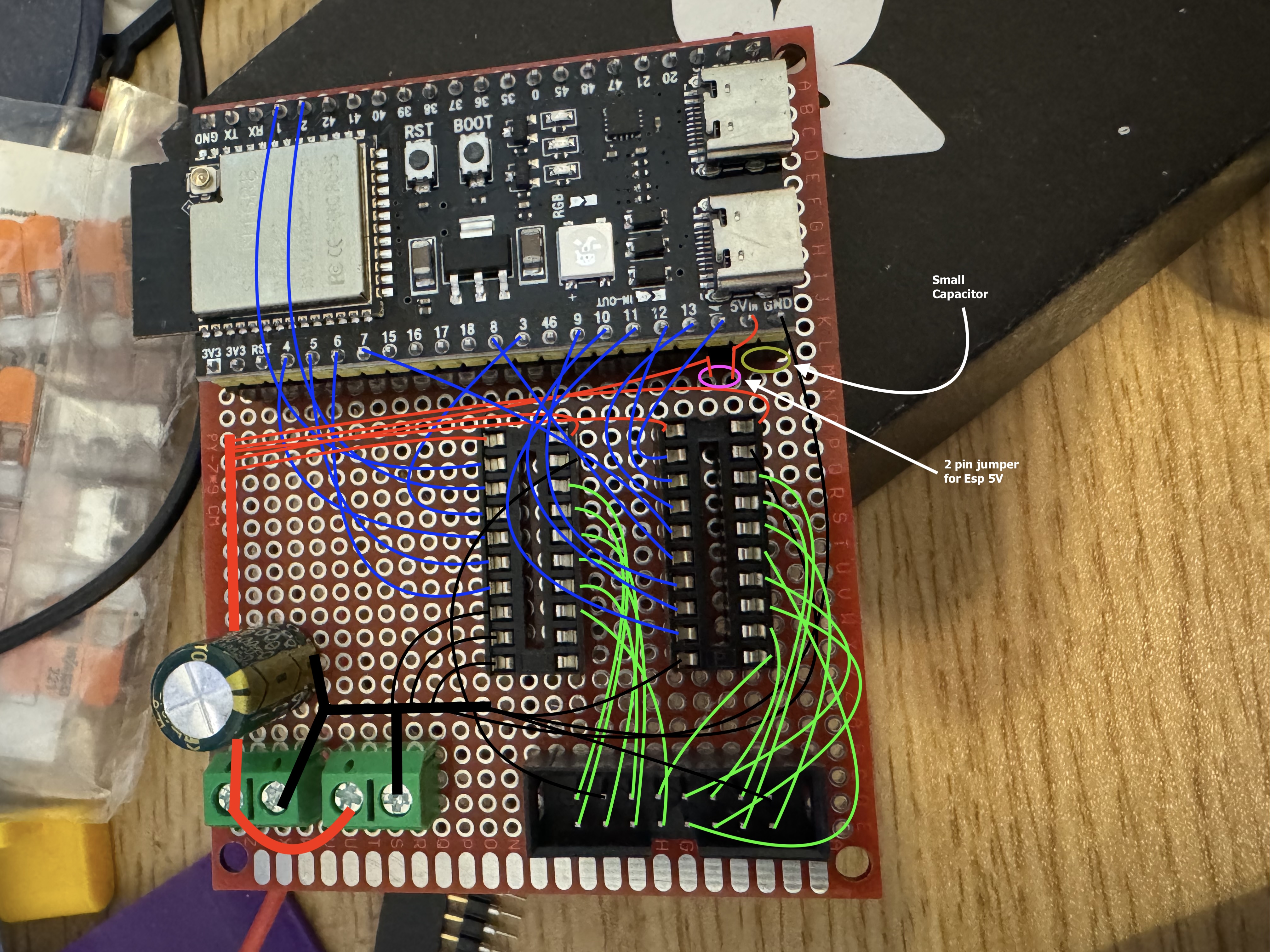
So we take a 7 cm x 9 cm perf board and get sockets to plug-in the ESP32-S3 and get two 20 pin dip sockets for the leveler chip and finally 16 pin hub 75 connector for the ribbon cable from the matrix panel. Also used two power connectors: one to plug the matrix panel in, and on to plug in our 5V (4 amp min) power source. We add a 2200µF capacitor to handle the power fluctuations when the panel when it draws. We also put a jumper in to allow us to separate the power of the ESP32-S3 when you’re flashing it. We take the jumper off when flashing via USB so the power doesn't backflow and cause damage.
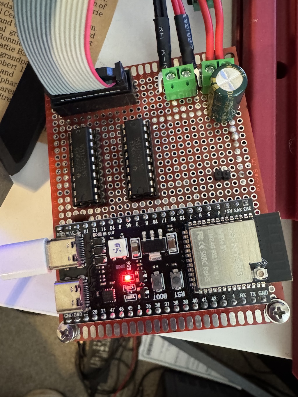
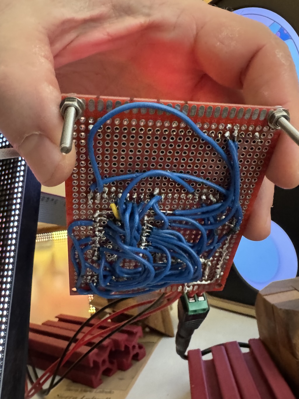
Now, I’m not very good at soldering, but I do know that flux will make your life a ton easier. Go slow, and use a voltmeter to confirm continuity where you intend and nowhere else. This may not be pretty but this works really and I get a rock solid super crisp picture on the panel.
But I don't want to solder!! I understand.
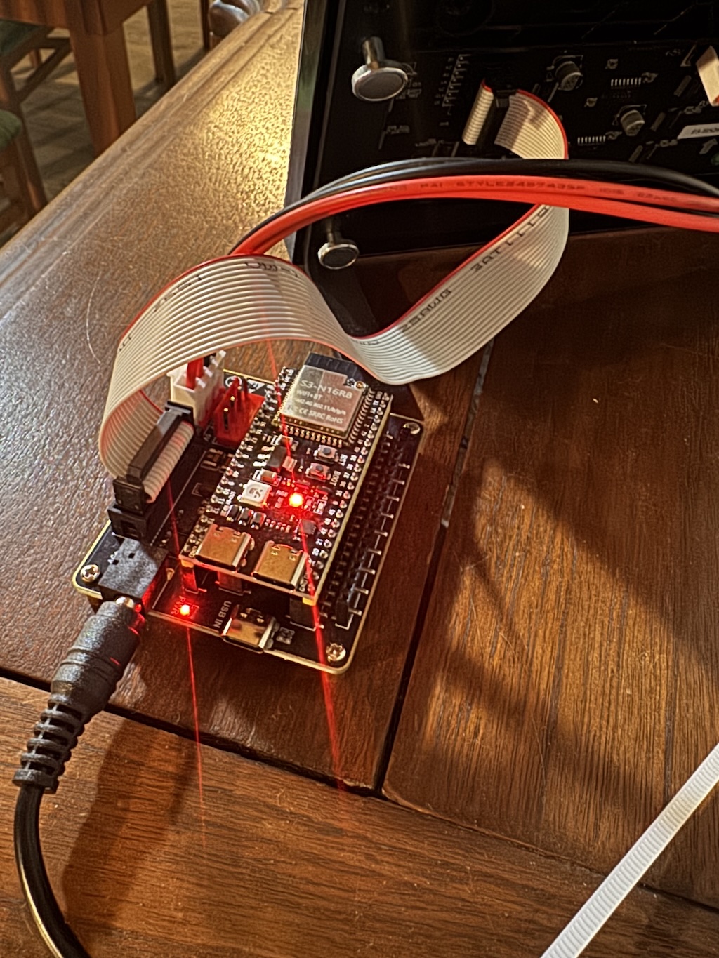
If soldering is not for you, Seengreat has a prebuilt board that works fine for this project as well.
If you wanted to take a stab at building this yourself, here is a parts list. It is cheaper to buy a board, but more enriching (in my opinion) to build your own.
Comments, ideas, feedback of any sort? Contact me!